


All Products
-
Sinotruk Howo Parts
-
Foton Auto Parts
-
FAW Auto Parts
-
Dongfeng Auto Parts
-
XCMG Spare Parts
-
Yutong Bus Parts
-
Sany Spare Parts
-
Liugong Spare Parts
-
JMC Auto Parts
-
Shacman Spare Parts
-
JAC Auto Parts
-
Shantui Spare Parts
-
Great Wall Spare Parts
-
Lifan Auto Parts
-
Weichai Engine Parts
-
Cummins Engine Parts
-
Gearbox Spare Parts
-
Xiagong Parts
-
Liuqi Chenglong Parts
Weichai Engine Parts New Fuel Injector Return Pipe 61500080095 Injector return line P10 weichai engine


| Place of Origin | CHINA |
|---|---|
| Brand Name | ORIGINAL |
| Certification | ISO9001 |
| Model Number | 61500080095 |
| Minimum Order Quantity | 15 PCS |
| Price | USD 5PCS USD4.9 20PCS USD4.8 200PCS |
| Packaging Details | carton |
| Payment Terms | L/C, D/A, D/P, T/T, Western Union, MoneyGram |
| Supply Ability | 2PCS 2 DAYS 20PCS 5DAYS 200PCS 7DAYS |

Contact me for free samples and coupons.
Whatsapp:0086 18588475571
Wechat: 0086 18588475571
Skype: sales10@aixton.com
If you have any concern, we provide 24-hour online help.
xProduct Details
| NAME | Weichai Engine Parts New Fuel Injector Return Pipe 61500080095 Injector Return Line P10 Weichai Engine | OEM NUMBER | 61500080095 |
|---|---|---|---|
| SIZE | 3*3*5 | Weight | 0.1KG |
| Packing | CARTON | PAY | Alibaba |
| TIME | 1-13 DAYS | Mode Of Transport | Air Car |
| Material | Iron | MOQ | 15 |
| Highlight | pipe Weichai Engine Parts,weichai fuel injector return pipe,6150080095 fuel injector return pipe |
||
You can tick the products you need and communicate with us in the message board.
| NAME | Weichai Engine Parts New Fuel Injector Return Pipe 61500080095 Injector return line P10 weichai engine | |
|---|---|---|
| MOQ | 15 | |
| MATERIAL | iron plastic | |
| OEM NUMBER | 61500080095 | |
| SIZE | 3*3*5 | |
| Time | 13 days |
Product Description
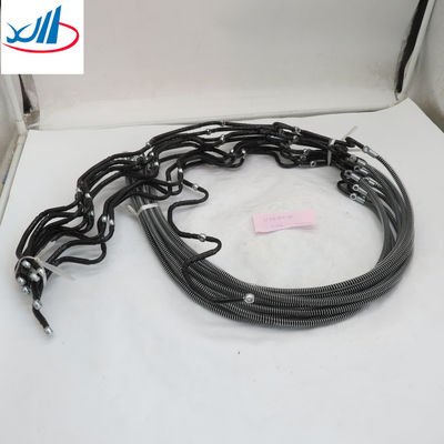
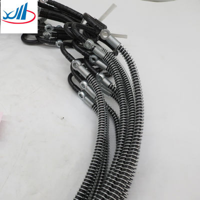
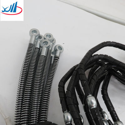
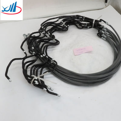
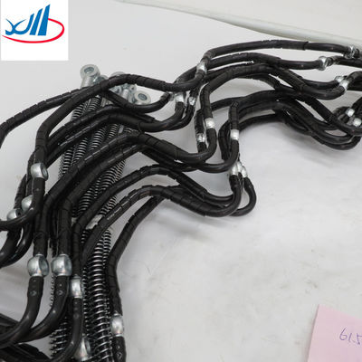
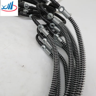
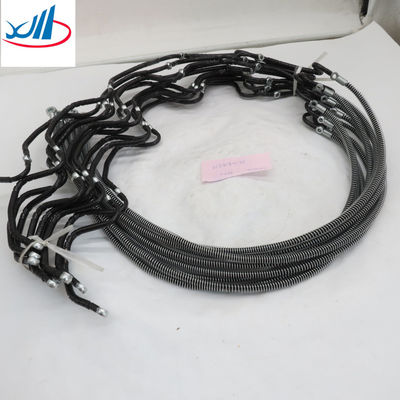
Weichai Engine Parts New Fuel Injector Return Pipe 61500080095 Injector return line P10 weichai engine
| Vehicle type | Building loader |
Certification |
ISO90002 |
Warranty period |
1 year | Delivery time | 2 DAYS |
Quality |
Original |
Material |
Iron |
| Name |
Weichai Engine Parts New Fuel Injector Return Pipe 61500080095 Injector return line P10 weichai engine |
Oem |
6150080095 |
| Sea | QINGDAO SHANGHAI NINGBO | Packing |
carton |
Product display
Weichai Engine Parts New Fuel Injector Return Pipe 61500080095 Injector return line P10
weichai engine
| Effect | It is possible to return excess oil to the tank, which can discharge the pressure of gasoline and reduce fuel consumption, not only to ensure that the inlet of the injection pump will not produce vaporization and cavitation due to too low oil pressure, but also to avoid cavitation to ensure the continuity of the oil supply of the high-pressure oil pump and make the engine work stable. |
| Production method |
Production method The utility model solves the technical problem of providing an engine fuel injection pump oil return pipe which prevents the air in the oil return pipe of the fuel injector from entering the engine fuel injection pump and affecting the oil pumping performance of the fuel injection pump. To achieve the above purpose, the utility model provides an engine fuel injection pump return oil pipe, which comprises an oil pipe drawn upward from an oil injection pump return hole and a fuel tank nozzle connected with the oil pipe. The return oil pipe of the fuel injector is connected by the connection point of the oil pipe and the oil tank nozzle. Further, the tubing is drawn vertically upward from the oil return hole of the injection pump. Further, the upper end of the oil pipe is arranged with a tee joint, and the oil tank nozzle and the return oil pipe of the fuel injector are connected with the oil pipe through the tee joint. According to the technical scheme of the utility model, since an oil pipe from the oil return hole of the fuel injection pump is added to the oil return pipe of the engine fuel injection pump, part of the oil return pipe is always retained in the oil return pipe of the fuel injection pump to seal the oil pipe during the oil return process of the fuel injection pump, so that the oil return pipe of the fuel injector cannot be directly connected to the oil return hole of the fuel injection pump, and the air in the oil return pipe of the fuel injector is prevented from entering the engine fuel injection pump. The pump performance of the fuel injection pump is affected, and the starting of the engine is affected. Figure 1 is a structural diagram of an engine fuel injection pump return pipe according to the utility model. The following is a specific implementation method of the utility model in combination with the attached drawings |
![]()
![]()
![]()
![]()
Recommended Products